Building the Perfect Travel Wii
Why Bother?
As a competitive Super Smash Bros. Melee player, I always have a Wii and CRT TV on hand to boot up a game of Melee. I’ve traveled to many different venues, and try to bring a setup when possible to help out the scene. Unfortunately, a full Melee setup is a lot to carry: a CRT TV, a Wii, the Wii’s power brick, and AV cables. I wanted something a bit more lightweight and easier to use. I set out to create a travel-optimized Wii at the lowest possible cost. The goal was under $100.
First Prototype
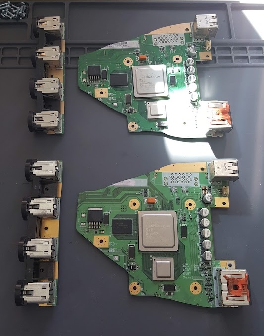 Two of the victims
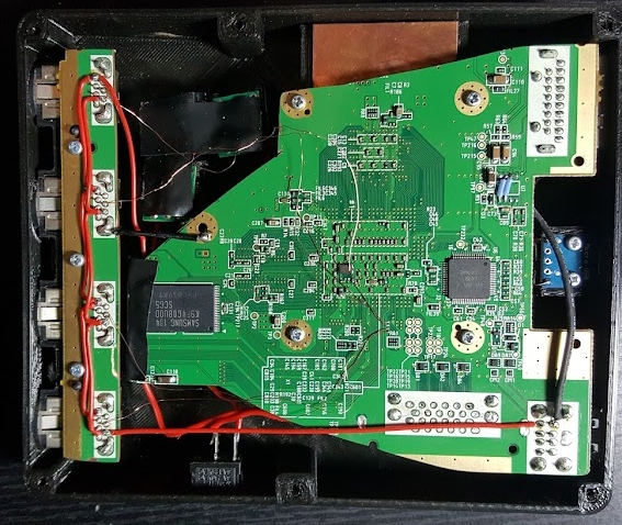
I built a total of three of these - two of them simultaneously after the initial prototype. This build features a more conservative trim of the Wii motherboard, preserving the USB ports, AV port, and all four of the heatsink screwposts. Since the minimum width of the build was constrained by the width of the GameCube controller ports, there’s nothing to gain by relocating these components. After sanding down the edges of the Wii motherboard and controller ports to prevent the inner layers of the PCB from shorting, I was almost ready to go on wiring things up. Before that, I needed to cut down and sand the sensor bar connector, which is on top of the AV connector. The added height of the sensor bar connector would limit the minimum thickness of the final product, which I wanted to be as slim as possible.
A short while with the dremel later, I got to work on the wiring. For this first prototype, I used the trusty PTH08080WAH voltage regulators that I had used in my first portable Wii to power the system. I then wired up the 5V, 3.3V, 1.15V, and 1V rails to system. I decided to use USB-C as the power source to supplement the need to carry around a power brick. This would allow the console to be powered from a simple phone charger. USB-C supports 15W at 5V (with an appropriate AC adapter), which is more than enough to power the ~7W that a (mid to late revision) Wii requires. This also allows the omission of a 5V voltage regulator, which reduces cost. Another design consideration I had to make was whether or not I should trim the GameCube controller port PCB down all the way. Trimming it as far as I did severed the 3.3V and 5V traces between the ports, so those would have to be manually rewired back together. A bit of a pain, but it reduces the minimum overall size of the build. Another minor setback I ran into was the audio pre-amp. 5V was not enough for it to reliably work, so I simply removed it and shorted the outputs to the inputs. The audio still sounds fine, but requires the TV audio to be turned up a bit extra.
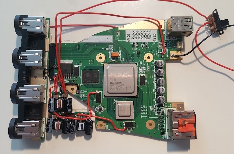 The Wii all wired up
3D Design
At this point, the project was electrically done, and it was time to start thinking about an enclosure. By doing the wiring first, I had a pretty good idea of the form factor that I wanted. A cooling solution did need to be kept in mind though as the 3D design came together. I used a similar cooling solution to that in my first portable Wii: a 35x35x7mm blower fan and adjacent 35x35x7mm heatsink with a copper plate to thermally connect them to the Wii CPU and GPU. Small dabs of thermal paste were placed on both sides of the copper plate. I started by rigorously recreating a 3D model of the Wii and all of its peripherals. I then designed the case around these models in the smallest form factor I could create. The enclosure was designed in three pieces: the top, which contained the mounting posts for all the PCBs, the walls, which contained the cutouts for the ports, and the bottom. It was done this way so that the ports could be friction fit into the holes before the rest of the case got in the way, due to it being such a tight fit in the x-y plane.
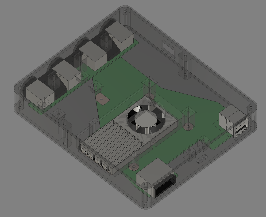 A look at the 3D models
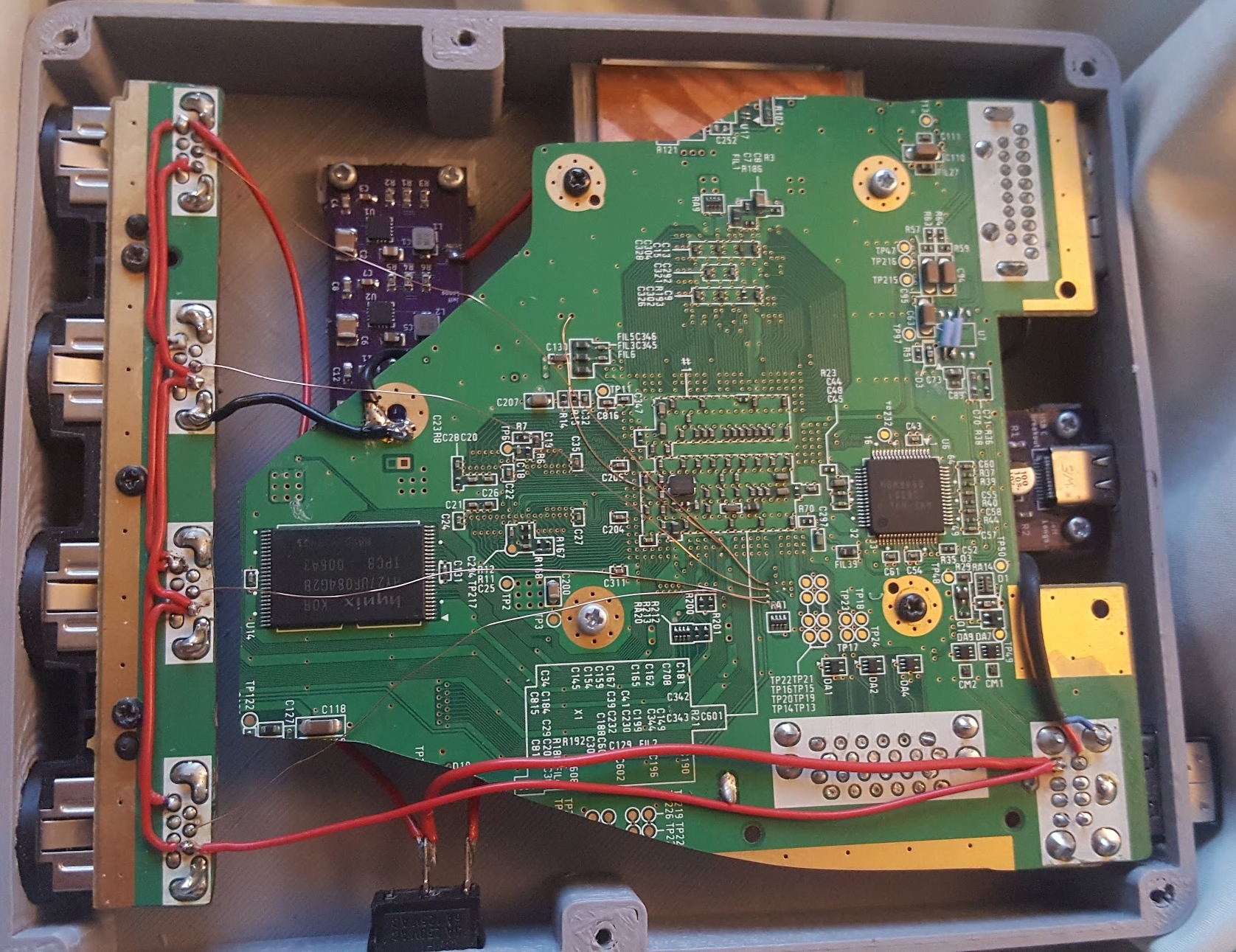
After several rounds of printing and tweaking the model, it was finally complete. I reused the screws from the Wii to assemble the final unit. The end result was some of the cleanest wiring I had done to date. I ended up selling this unit, which gave me an excuse to improve the design.
 Internals of the first prototype
Take Two
The second time around, I made some adjustments to the design. First, I created a custom PCB to replace the PTH08080WAH voltage regulators. This allowed for a cleaner wiring job and another thing that could be screwed down into the case. I also created a USB-C connector board to replace the off-the-shelf one I was using, which could not be secured to the case as well as I liked. Lastly, I printed the case using the PEI powder-coated textured bed for my 3D printer. This gave the outside of the case a far more polished look.
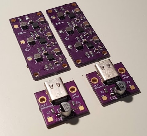 Custom power PCBs for revision 2
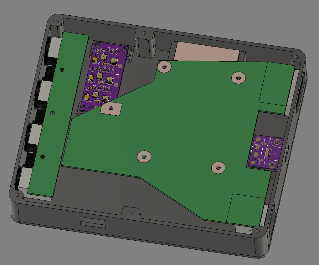 Updated case design
I ended up very happy with the final product. With these modifications, everything slots in perfectly and very little extra wiring is necessary. I was able to build both of the second-revision units from assembled Wii to assembled Wii Micro in one day. I ended up selling one of those two, but I hold on to the third one to this day. It has endured hundreds of hours of gameplay and still works like a charm.
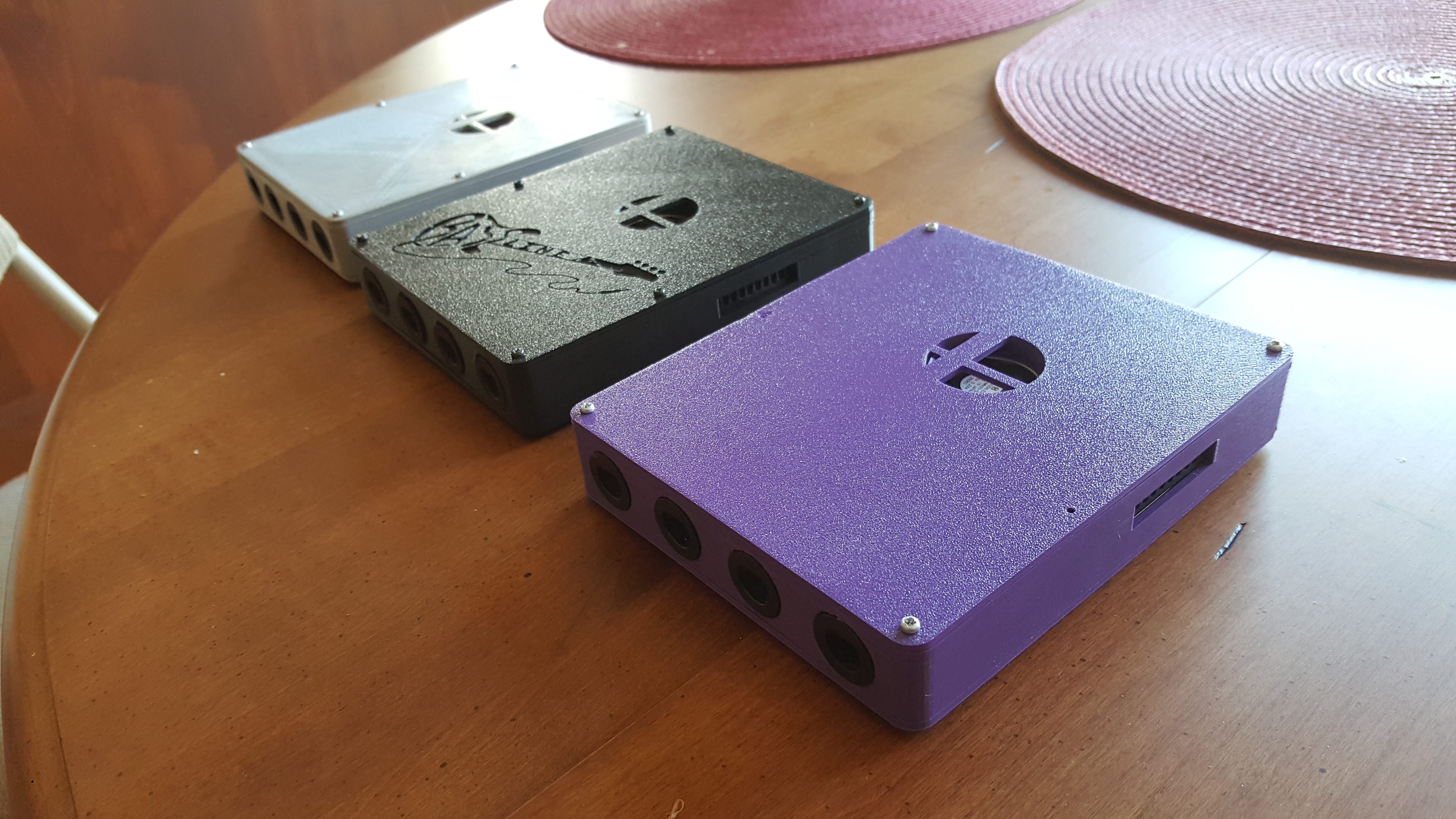
 The final product
Retrospective
This project taught me a lot of new things. It was the first time I had seriously designed my own PCB for a finished project. It was the first time I had done my own 3D printing (and all the tuning that comes with it…). I have to say that my favorite thing about this project, though, is that I use it all the time. Many of my projects I build because they’re fun to design and build, but I often hardly use them after they’re built. I’ve taken this project to many Smash tournaments, and use it at home whenever I want to play on a Wii. There’s something great about that.
See the full worklog here.