GameCube Controller Reverse Engineering (Part 1)
Motivation
I’m not the first one to reverse engineer the GameCube controller protocol. However, a lot of the information out there is either incomplete or inacccurate. With the intent to emulate the GameCube controller protocol on a microcontroller, I took a deep dive into understanding the protocol.
Physical Interface
The first step in reverse engineering a hardware protocol is to inspect the physical interface. The GameCube controller protocol is actually an extension of the Nintendo 64 controller protocol, which uses single-wire bidirectional communication. The data wire is open drain meaning it is pulled-up via a pull-up resistor (to the 3.3V rail) and when the console or controller wants to talk on the bus, they drive the line low to communicate. This prevents collisions on the bus and is used for other bidirectional single-wire data line protocols such as I2C.
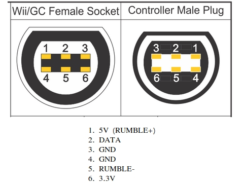 GameCube controller pinout
What makes the GameCube/N64 protocol interesting is the omission of a clock. Most common protocols have a data line and a clock line, where the clock gives a reference for when to read the data line to check if the current bit is a 1 or a 0. Because there is no clock, there must be timing pattern to indicate 1s or 0s.
Capturing the Protocol
The next step after identifying the interface is to capture it in action. One way to do this would be to use an oscilloscope, which creates a graph of voltage versus time. However, because we know that this protocol is a digital protocol (1s and 0s) a logic analyzer is preferable. A logic analyzer performs the same function as an oscilloscope, but only shows 1s and 0s instead of an analog waveform. This means that it’s possible to capture a lot more data in a lot smaller file size, and it’s easier to analyze.
To take this capture, I opted to use a Saleae Logic Pro 8. It is compatible with their Logic 2 software which is an absolutely fantastic piece of software. It is much more intuitive and user-friendly to use than alternatives such as PulseView. The huge advantage to using the Logic software is that it allows you to build a protocol decoder. A protocol decoder can run on a waveform and display it in a user-readable format, instead of inspecting it one bit at a time. The Saleae Logic hardware is no doubt quite expensive. There are, however, cheap knock-offs that also work with the Logic software. They can get the job done, but in my experience only work at pretty slow sample rates, are prone to randomly disconnecting, and do not have the ability to capture analog data as well. The official hardware is well worth the investment.
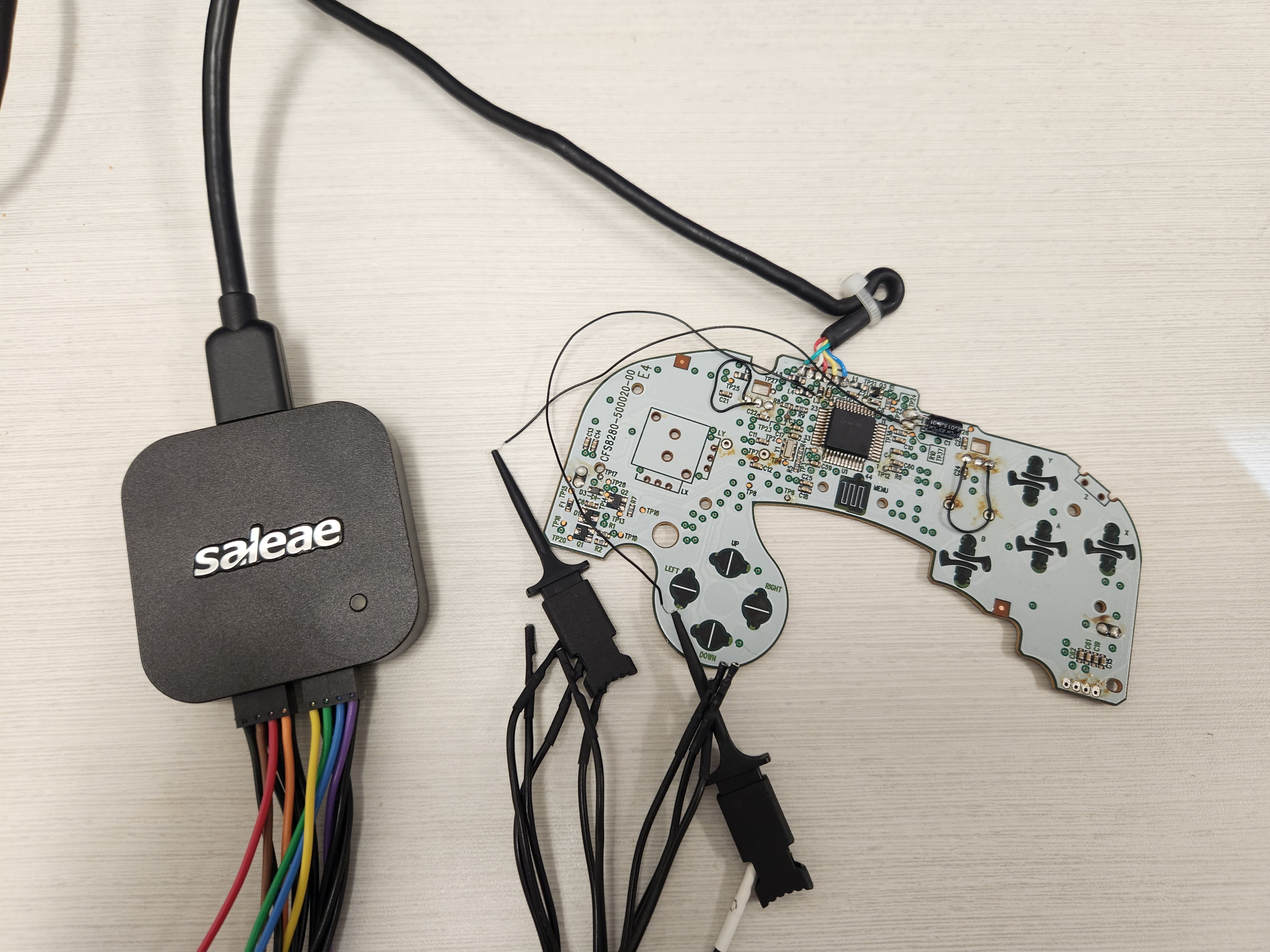 Saleae Logic Pro 8 connected to GameCube controller
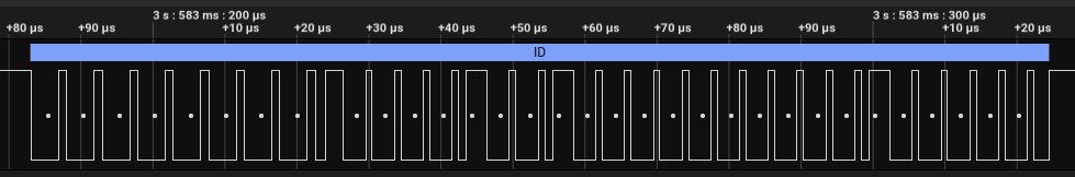
Equipped with the Saleae Logic, I took some captures of controller’s data line. The protocol is a command/response interface; the console sends a command, and the controller sends a response. Bits are encoded based on the low time of the signal. The console sends bits with a period of 5us, while the controller sends bits with a period of 4us. A 0 is encoded by driving the line low for 75% of the period, and releasing it for the remaining 25%. A 1 is encoded by driving the line low for 25% of the period, and releasing it for the remaining 75%. When the command or response is completed, a 1 bit is sent as a stop bit. The timings are summarized below.
| Bit | Low time (us) | High Time (us) | Total Period (us) |
|---|---|---|---|
| 0 (console) | 3.75 | 1.25 | 5 |
| 0 (controller) | 3 | 1 | 4 |
| 1 (console) | 1.25 | 3.75 | 5 |
| 1 (controller) | 1 | 3 | 4 |
When there is no controller plugged in, the console polls for controllers by sending the ID command repeatedly until a controller responds. If a controller fails to respond within ~65us of receiving a command, the console will start sending the ID command again.
Reset Command (0xFF)
A reset command notifies the controller to reset, then responds as if it received an ID command.
ID Command (0x00)
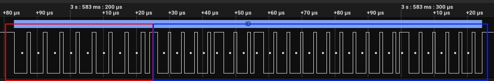 ID command
In this image, the ID command issued by the console is displayed in red. Note the 8 low bits followed by a high stop bit. The controller responds with a 3 byte bitmap, which tells the console some information about itself, followed by a stop bit. The first 2 bytes describe the type of controller, described in the table below (source). This table is incomplete. Please reach out if any more accurate information can be provided.
ID Response Bytes 1 and 2
| Bit | Description |
|---|---|
| 15 | Controller is wireless (1 = yes) |
| 14 | Controller supports wireless receive? (1 = yes) |
| 13 | Controller supports rumble (0 = yes) |
| 12 | Controller type (always 0? maybe reserved for future consoles?) |
| 11 | Controller type (0 = N64, 1 = GameCube) |
| 10 | Wireless type (0 = IF, 1 = RF) |
| 9 | Wireless state (0 = variable, 1 = fixed) |
| 8 | Non-standard controller (1 = standard GameCube controller) |
| 7 | ? |
| 6 | ? |
| 5 | Wireless origin (1 = valid) |
| 4 | Wireless fix id (1 = fixed) |
| 3 | Wireless type (0 = normal, 1 = non-controller?) |
| 2 | Wireless type? |
| 1 | Wireless type? |
| 0 | Wireless type? |
The third byte describes the current status of the controller. This byte is context dependent (the content is different for N64 controllers compared to GameCube controllers).
ID Response Byte 3
| Bit | Description |
|---|---|
| 7 | Error (1 = error on last transfer) |
| 6 | Error (latched) |
| 5 | Origin has been sent to console (0 = yes) |
| [4:3] | Rumble mode |
| [2:0] | Poll mode |
Status Command (0x40)
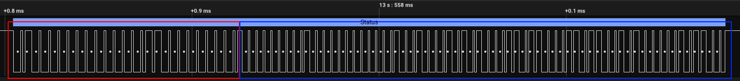 Status command
The status command is the most important command. It sends the console the current state of the buttons, joysticks, and shoulders, controls the format they are sent in, and controls rumble. In contrast to the previous commands, the status command has 2 argument bytes that are sent by the console after the command byte. The first argument is the poll mode and the second argument byte is the rumble mode.
Status Command Argument Bytes
| Byte | Description |
|---|---|
| 1 | Command |
| 2 | Poll mode |
| 3 | Rumble mode |
Rumble Mode
The rumble motor can be in one of three states:
- Off (rumble mode = 0)
- On (rumble mode = 1)
- Brake (rumble mode = 2)
When the motor is in the on state, 5V is applied to RUMBLE+ and 0V is applied to RUMBLE-. The motor will vibrate. When the motor is in the off state, 5V is applied to RUMBLE+ and RUMBLE- is left open circuit. The motor will stop vibrating. When the motor is in the brake state, 0V is applied to RUMBLE+ and 0V is applied to RUMBLE- (they are shorted). The motor will abruptly stop vibrating.
Poll Mode
There are 5 poll modes that the console can choose from. The poll mode determines the format of the analog values in the status response. Poll mode 3 is by far the most commonly used format. It allows full 8-bit resolution of all the (used) analog inputs. Luigi’s Mansion infamously uses poll mode 0.
Status Response (poll mode = 0)
| Byte | Description |
|---|---|
| 1 and 2 | See here |
| 3 | Joystick X |
| 4 | Joystick Y |
| 5 | C-Stick X |
| 6 | C-Stick Y |
| 7 | [7:4] L Analog [3:0] R Analog |
| 8 | [7:4] A Analog [3:0] B Analog |
Status Response (poll mode = 1)
| Byte | Description |
|---|---|
| 1 and 2 | See here |
| 3 | Joystick X |
| 4 | Joystick Y |
| 5 | [7:4] C-Stick X [3:0] C-Stick Y |
| 6 | L Analog |
| 7 | R Analog |
| 8 | [7:4] A Analog [3:0] B Analog |
Status Response (poll mode = 2)
| Byte | Description |
|---|---|
| 1 and 2 | See here |
| 3 | Joystick X |
| 4 | Joystick Y |
| 5 | [7:4] C-Stick X [3:0] C-Stick Y |
| 6 | [7:4] L Analog [3:0] R Analog |
| 7 | A Analog |
| 8 | B Analog |
Status Response (poll mode = 3)
| Byte | Description |
|---|---|
| 1 and 2 | See here |
| 3 | Joystick X |
| 4 | Joystick Y |
| 5 | C-Stick X |
| 6 | C-Stick Y |
| 7 | L Analog |
| 8 | R Analog |
Status Response (poll mode = 4)
| Byte | Description |
|---|---|
| 1 and 2 | See here |
| 3 | Joystick X |
| 4 | Joystick Y |
| 5 | C-Stick X |
| 6 | C-Stick Y |
| 7 | A Analog |
| 8 | B Analog |
The astute reader will notice mention of an A and B analog. This was likely a feature that was dropped for production. In fact, I’m pretty confident that there are A and B analog pins on the controller ASIC that probably work and are left unconnected. It would be interesting to see if someone were to find them and apply voltage to them if they would respond accordingly in the response.
Status Response Bytes 1 and 2
The first 2 bytes in the response of a status command describe the state of the controller’s buttons and status, shown in the table below.
| Bit | Description |
|---|---|
| 15 | Use the controller origin (1 = yes, not confirmed) |
| 14 | L (1 = pressed) |
| 13 | R (1 = pressed) |
| 12 | Z (1 = pressed) |
| 11 | D-Pad Up (1 = pressed) |
| 10 | D-Pad Down (1 = pressed) |
| 9 | D-Pad Right (1 = pressed) |
| 8 | D-Pad Left (1 = pressed) |
| 7 | Error (1 = error on last transfer) |
| 6 | Error (latched) |
| 5 | Origin has been sent to console (0 = yes) |
| 4 | Start (1 = pressed) |
| 3 | Y (1 = pressed) |
| 2 | X (1 = pressed) |
| 1 | B (1 = pressed) |
| 0 | A (1 = pressed) |
Poll Rate
Because the GameCube had no kernel, controller polling is done completely in hardware. The console configures the poll rate by configuring the number of horizontal lines that are rendered between successive polls (source). Many games poll at 60Hz, but some games, such as Super Smash Bros. Melee, poll at 120Hz. The console is capable of polling at speeds as high as 2KHz.
Origin Command (0x41)
 Origin command
The origin command tells the console what the state of the controller was when it came out of reset. It is used to calibrate the analog controls if they are naturally uncentered. The origin value gets subtracted off of any given analog input before a game processes it. For example, if the joystick x-axis origin was at x = 5 (assume center is 0), and the current value is 5, the value a game would use would be the current value minus the origin value, resulting in a value of 0. In other words, it “shifts” the joystick’s center to the origin value. This command (or a recalibrate command) immediately follows the response of an ID command. The controller responds with 10 bytes. The first 2 bytes are the same as the first 2 bytes in the response to a status command. When the console requests a controller’s origin, the Origin has been sent to console bit in the ID, origin, and status commands are cleared.
The remaining 8 bytes describe the analog inputs. These bytes are described in the table below.
Origin Response Bytes 3 to 10
| Byte | Description |
|---|---|
| 3 | Joystick X |
| 4 | Joystick Y |
| 5 | C-Stick X |
| 6 | C-Stick Y |
| 7 | L Analog |
| 8 | R Analog |
| 9 | A Analog |
| 10 | B Analog |
Recalibrate Command (0x42)
 Recalibrate command
This command is functionally very similar to the origin command. It tells the controller to capture new origin values and report them to the console. The response format is the same as an origin command. However, it does have 2 command arguments like the status command. It’s unclear whether these arguments are used. They are both always 0x00. This command is sometimes used instead of the origin command. For example, when booting up the GameCube or Wii system menu.
“Long” Status Command (0x43)
This command was found by fuzzing the controller and is apparently only used by the GameCube Service Disc (source: Extrem). It has 2 command arguments, like the recalibrate command, that are possibly unused. It returns the controller status in the 10 byte format of an origin.
To Be Continued..
Check out part 2 here.