GameCube Controller Reverse Engineering (Part 2)
This is a continuation to GameCube Controller Reverse Engineering (Part 1). Be sure to check that out if you haven’t already.
Decoding the Commands
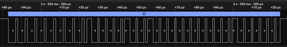
To validate all of the previous protocol research, I created a protocol decoder for the Saleae Logic 2 software. Feel free to download it and try it here. Not only did this allow me to annotate commands so I could identify commands at a high level, but the recent addition of FrameV2 support allows me to generate a table of command outputs to easily see the different fields of a command-response frame. The software also allows you to jump to a particular frame by selecting it from the table. The frame table can also be easily searched or exported for further analysis.
 Annotated commands
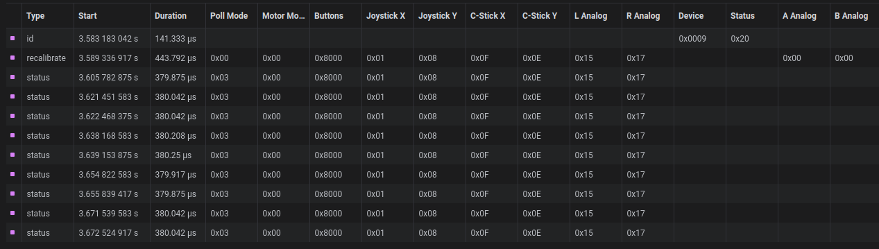 Frame table
Here are some captures if you want to take a look at them in the Logic 2 software.
Designing a Replacement Chip
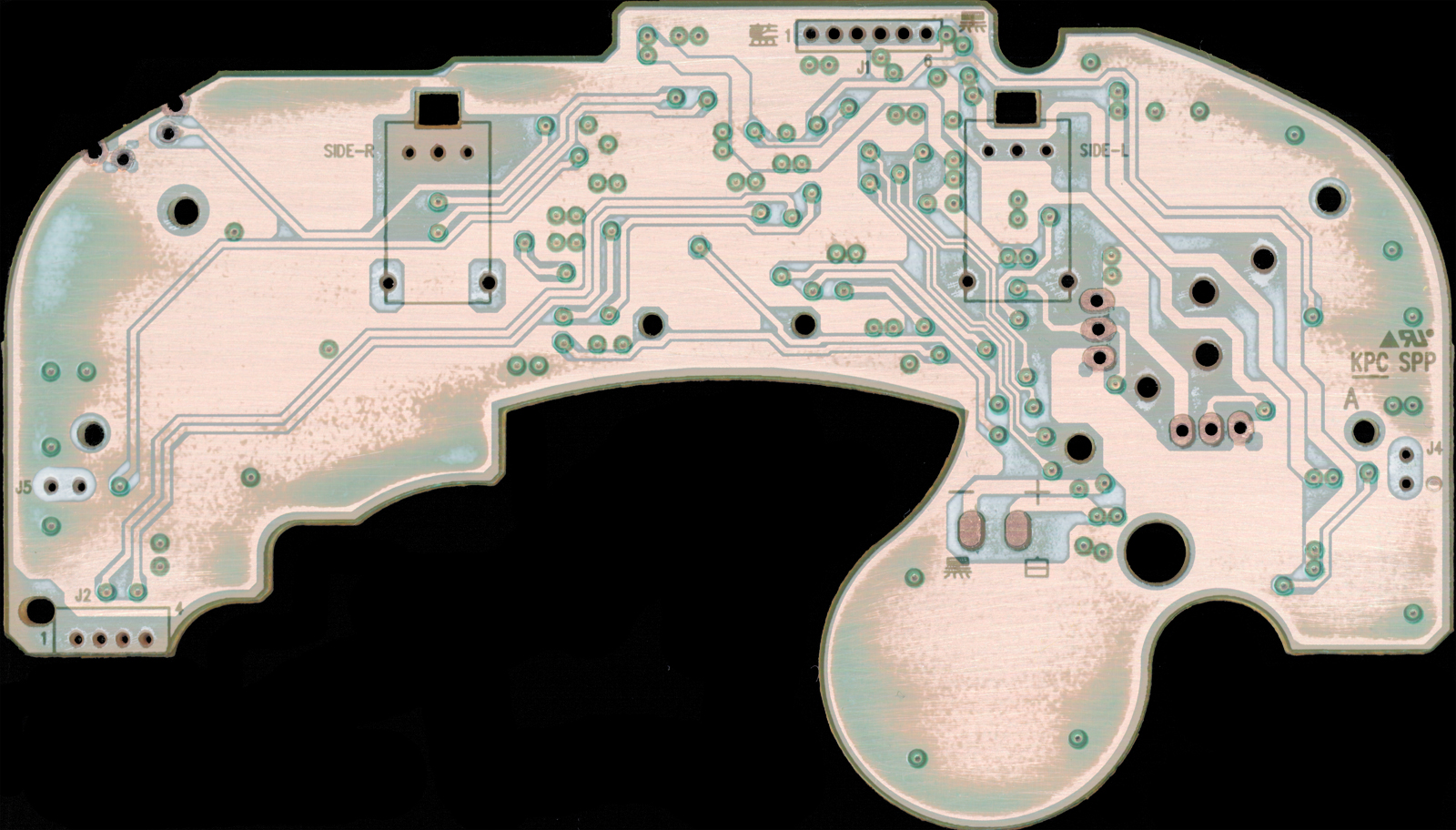
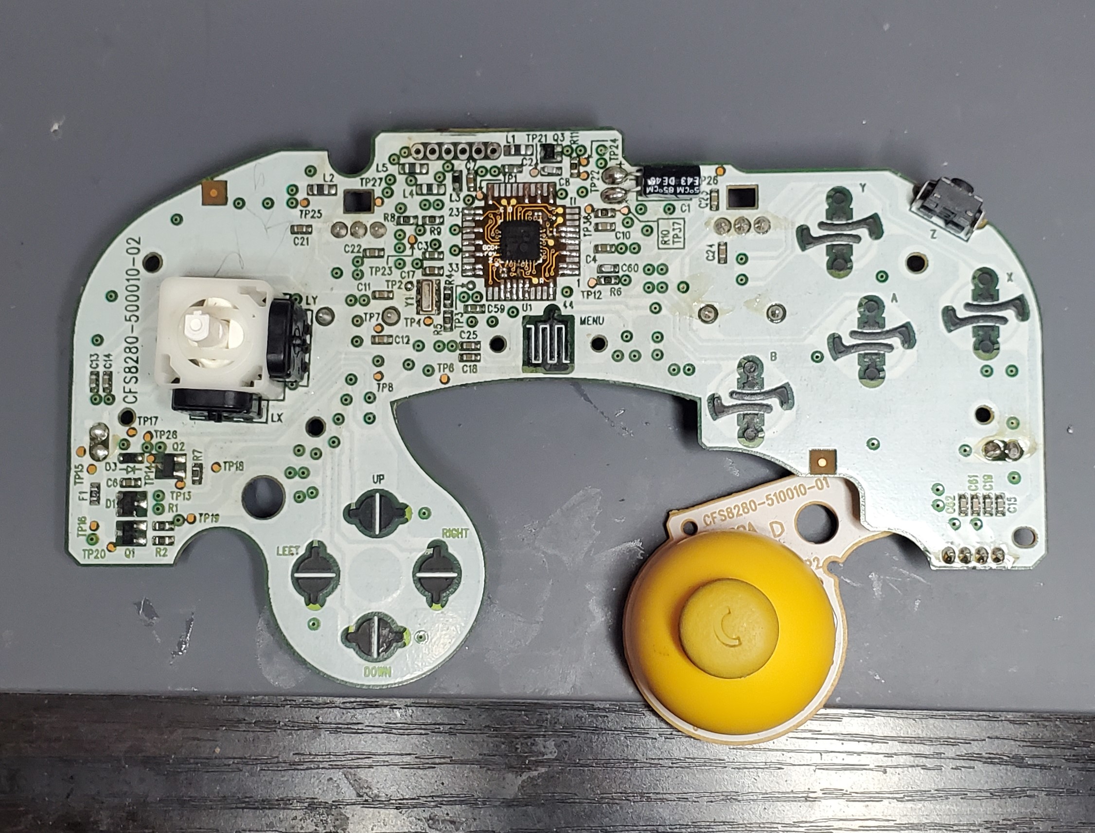
After I had a solid grasp on the protocol, I wanted to see if I could replace the ASIC on an OEM GameCube controller with a very small carrier PCB containing a microcontroller - the idea being that the carrier PCB would have castellated edges that could solder down directly to the footprint of the ASIC. Before I could do that, I had to figure out the pinout of the existing ASIC. To do that, I found some scans of the OEM PCB on Acid Mods forum. Unfortunately, the scans weren’t very high quality, due to the compression of the forum. I contacted the original poster, RDC, and he was generous enough to send me the original high quality scans. I was able to map out the pinout of all the analog and digital inputs, and also discovered that original ASIC is clocked from a 4MHz oscillator. I added an option to use it on my custom PCB.
 |  ) ) |
Now that I had a pinout, I was able to take a crack at making my own board. My first attempt used OSHPark’s 0.8mm service to make the board as thin as possible. Unfortunately, it was still pretty difficult to solder down, and I didn’t get the pitch quite right on the pads.
 First attempt at the PCB
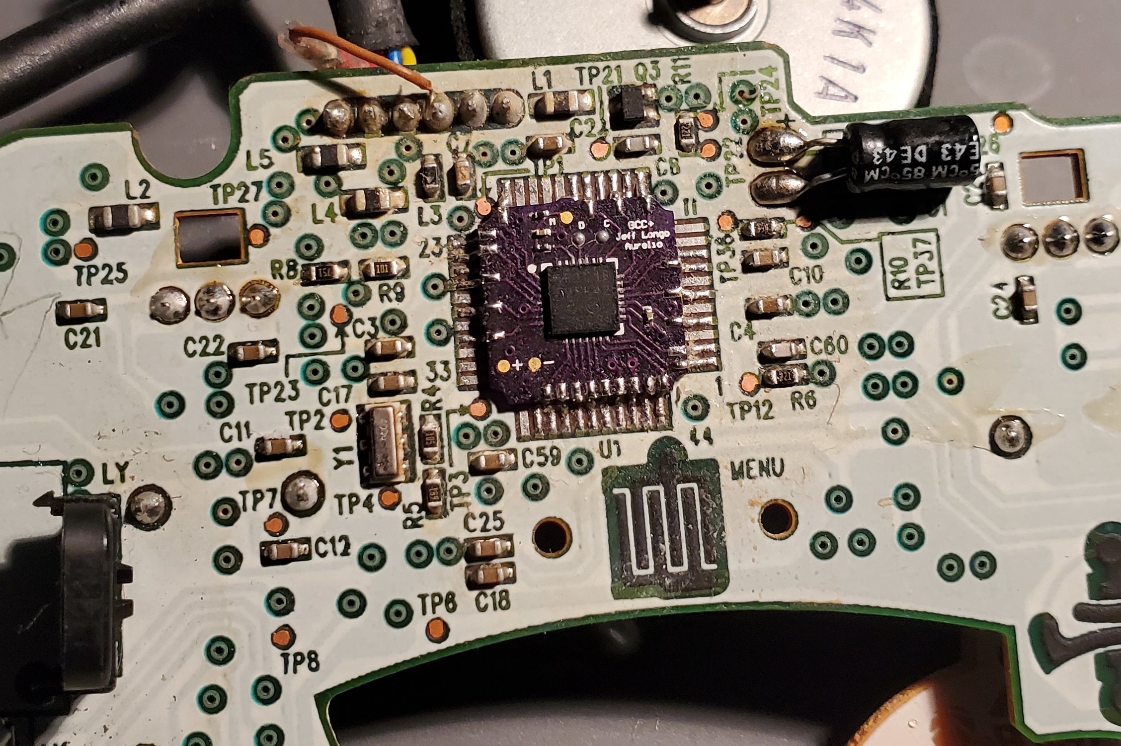
For the second attempt, I switched to OSHPark’s flexible PCB service. The cost difference was negligible with a PCB so small. This time it fit perfectly. I implemented the controller protocol using an STM32 microcontroller.
 Second attempt at the PCB. Much better!
And there it was! I had a working GameCube controller (again). Although it isn’t any better than a regular controller, it was a very interesting project academically, and it opens up opportunities for creating a full replacement board down the line. There will be more to come.