From Knowing Nothing to Building a Portable Wii
The Beginning
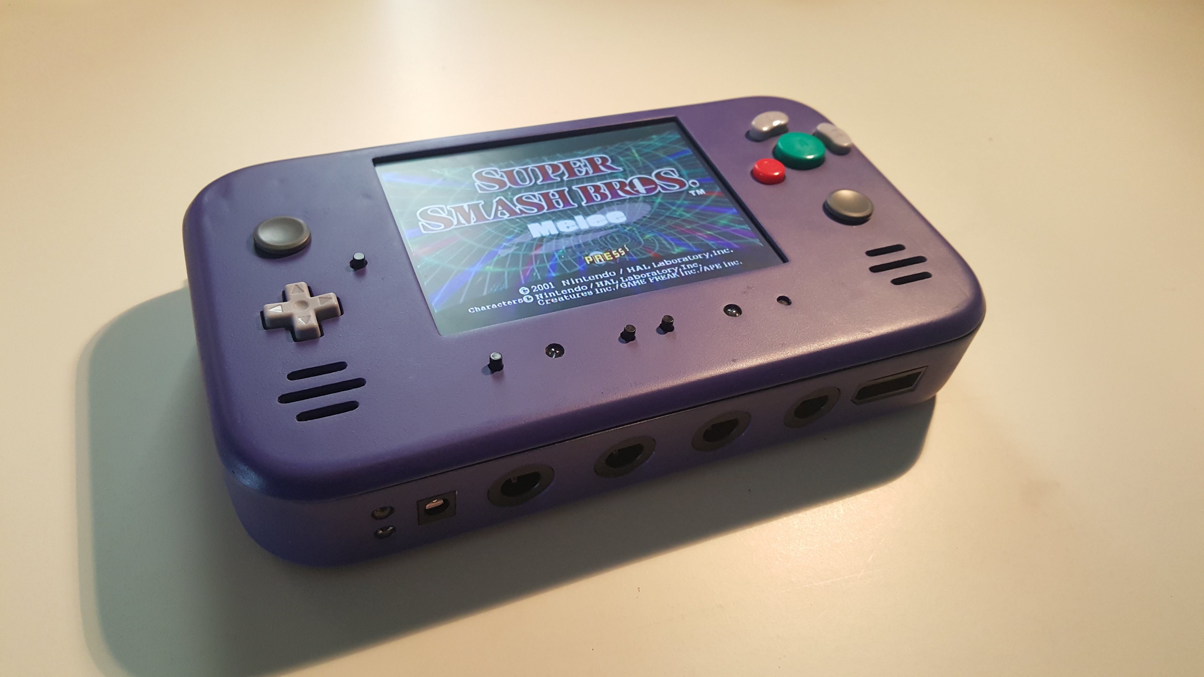
I somehow stumbled across this video of a portable GameCube. I was instantly obsessed and knew I had to make one too. At this point in time, I had recently graduated high school, and had zero experience working with hardware in any capacity. Without a clue on how to proceed, I desperately tried reaching out to the author of the video, Zack Hale. I was shocked when he actually responded and offered his guidance at any time.
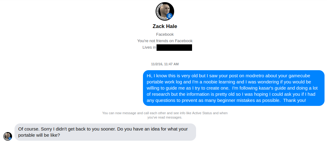 Conversation with Zack Hale
After going back and forth with Zack for some time, I was eventually led to Kasar’s GameCube portable guide on ModRetro which became my bible. With the sacred texts at hand, I determined what I would need to build the portable. I wanted to make a replica of Zack’s portable GameCube.
- A GameCube (not a Wii yet, more on this later..)
- Some way to remove the enormous disc drive and replace it with an SD card or USB drive
- Batteries to power the console and a BMS for charging
- A controller to embed into the portable
- A memory card to store game data
- A display
- Speakers
- An enclosure to house everything in
I began sourcing all the parts. To replace the disc drive, I picked up a (no longer produced) WASP fusion modchip, which allows GameCubes to boot games from an SD card. I got some 18650 cells for powering the console, and I chose the same ZN40 case from Polycase that Zack had used for his portable.
The First Attempt
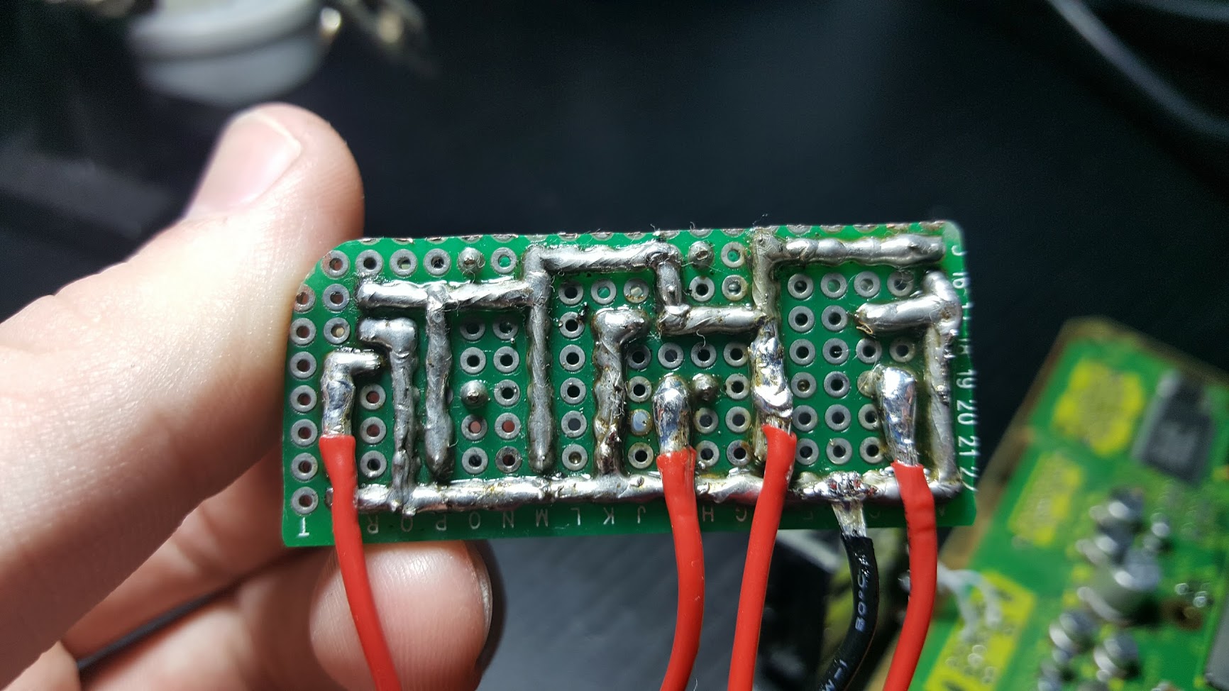
I had never attempted soldering before. My first task to get started would be relocating the memory card. I (forcefully) removed the memory card ports from the GameCube motherboard and soldered a memory card PCB directly to the port vias. I also soldered an SD card socket to the other memory card port (a GameCube memory card is basically just an SD card) which would be used to load the homebrew that allows the SD card game loading.
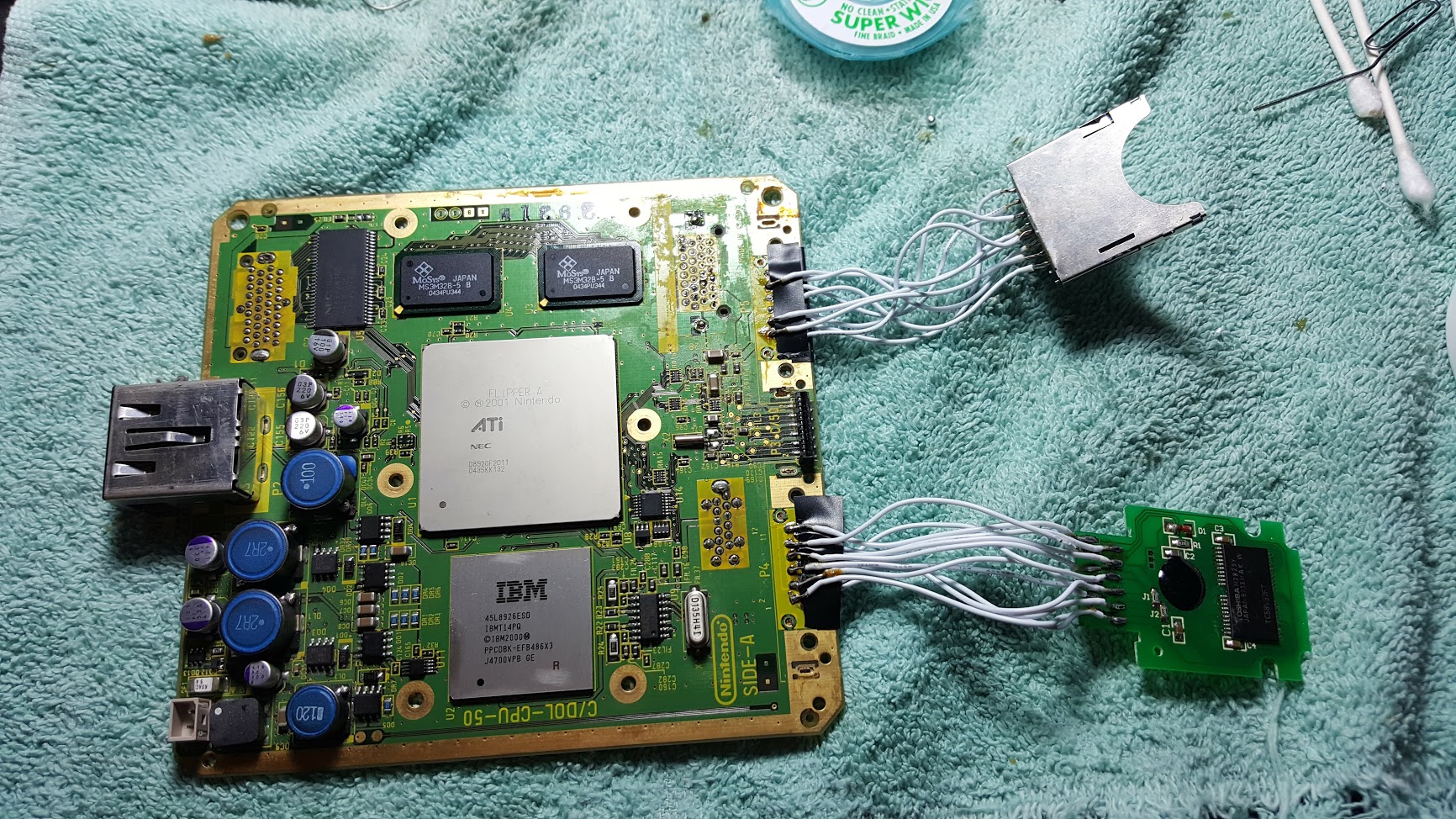 The first solder joints
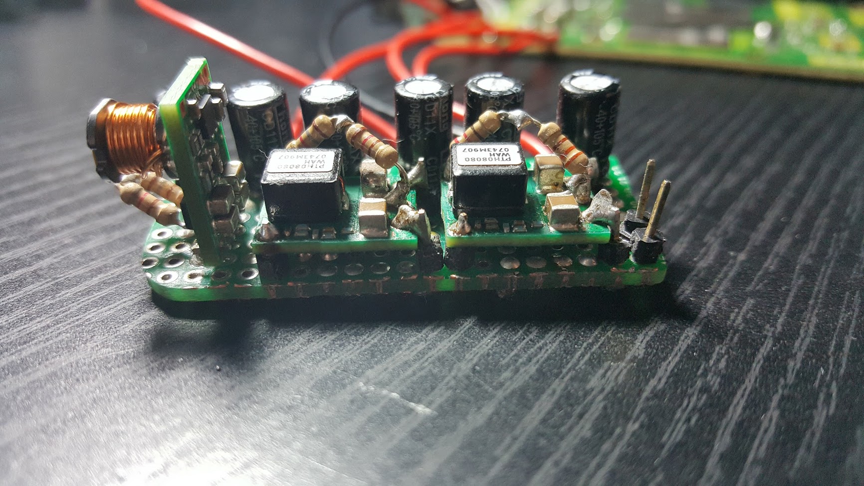
As it often happens, I decided to go down the rabbit hole of trimming the motherboard (cutting off the non-important parts of the board with a rotary tool) and using custom voltage regulators to improve the efficiency and reduce the motherboard size footprint. I created a voltage regulator module using several TI PTH08080/PTR08060 modules to provide the GameCube with 5V, 3.3V, and 1.9V.
 |  |
To make things even more complicated, I decided that this portable would have video out via the OEM composite video port, and 4 GameCube controller ports to plug in external controllers. Sometimes you need to walk before you run, and that’s a takeaway I would soon discover. In addition, it was around this time I joined the BitBuilt modding community, where the resounding advice was to use a Wii for making a portable GameCube instead of a GameCube itself. The Wii can natively run GameCube games, can load games from USB without requiring a modchip, produces half the heat and draws half as much power. But at this point, I was too stubborn and invested to not see the GameCube portable through with what I had. I had wired up pretty much everything, I had the case laser cut by a friend to have the cutouts I would need, and I just needed to put everything in the case and close it up. Easier said than done.
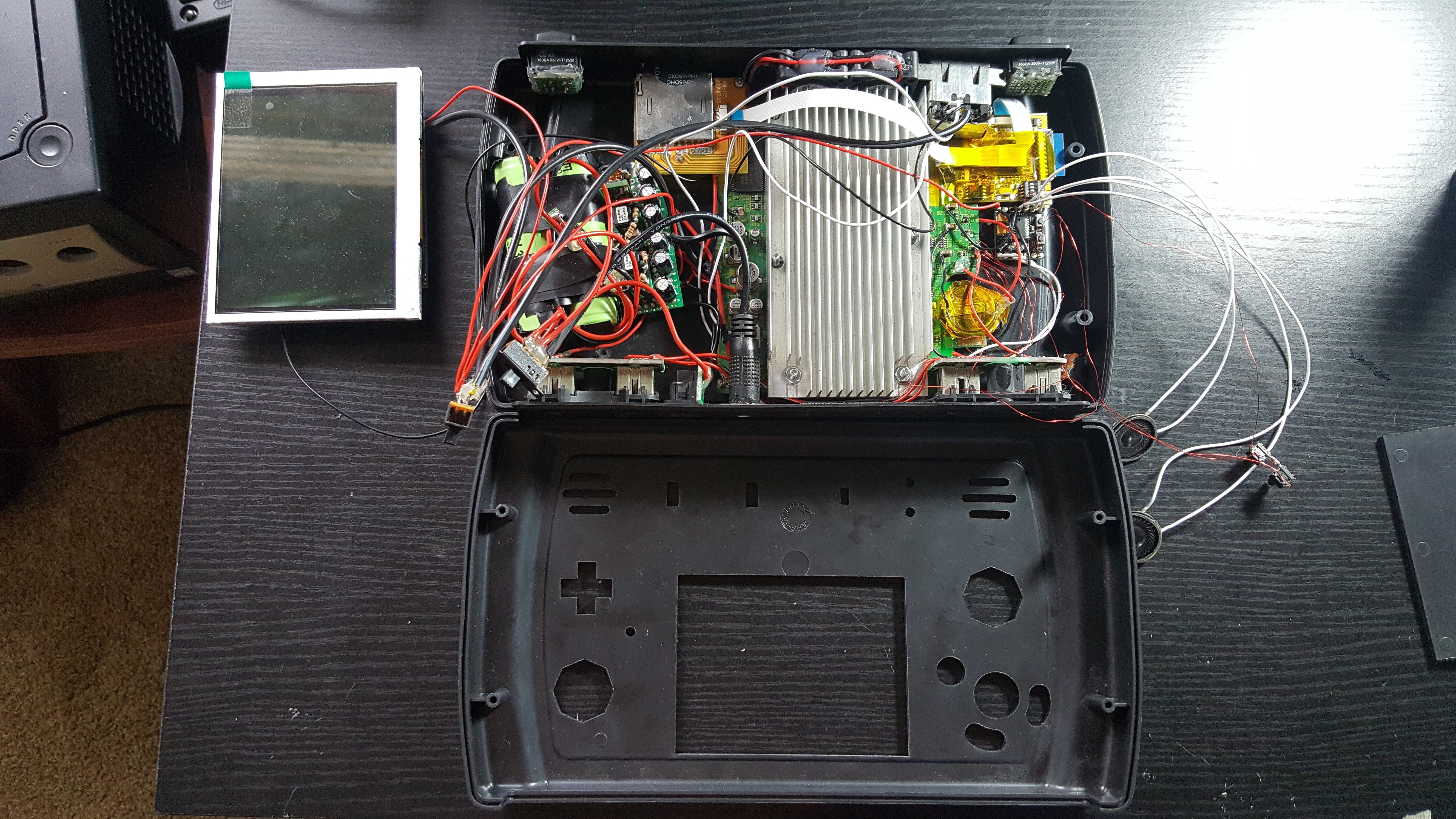 In retrospect the internals were hideous
This is when disaster struck. After many successful boots, the board inexplicably started smoking. To this day I’m unsure if it was my fault or something out of my control. Apparently, trimmed GameCube motherboards are pretty volatile. This is when I finally gave in and decided to restart everything from scratch with a Wii.
The Switch to Wii
I picked up a Wii off of Craigslist for $10, and got to work. I installed the required software, trimmed the motherboard, and built a new set of custom voltage regulators (the Wii uses 5V, 3.3V, 1.15V, and 1V). The Wii can be trimmed shockingly small. Nearly all the components required for a Wii to work (the CPU, GPU, RAM, and NAND flash memory) are all located nearby each other. It’s really not as hard as it looks, either.
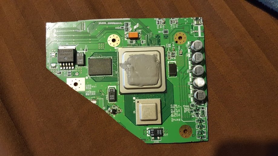 Trimmed Wii motherboard
The plan was to cram these new internals into the existing case. While I was working towards this, I was growing increasingly resentful towards the case. It was at this time that hobbyist 3D printing was becoming mainstream and affordable. The future of portablizing was shifting towards 3D printing a custom enclosure instead of “frankencasing” an enclosure together. A 3D printed enclosure can be entirely customized for the project at hand. If designed right, one can add screwposts for everything. This makes the assembly cleaner and prevents you from having to use glue. 3D CAD was entirely foreign to me, but I thought it would be a fun thing to learn. I tried out Fusion 360 because it is free for hobbyists and is much more versatile than primitive CAD tools like SketchUp. After what’s likely to be close to 100 hours, I finally had a case ready to print.
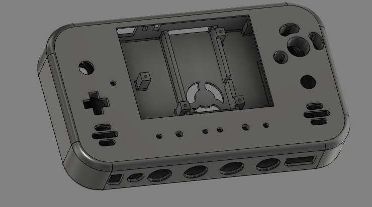 3D model of the case
I painstakingly measured dimensions and cutout sizes using a caliper. The cutouts for the stock GameCube buttons were particularly challenging to recreate. The other challenge was that I did not own a 3D printer at the time. Furthermore, this was before the time you could affordably purchase 3D models from online services. Luckily, I had a friend in Texas who was willing to print the case for me. However, that was not at all close to me, so the case needed to be shipped. Which means I’d better get all the dimensions right, or there would be a long time between test prints. Everything fit on the second attempt, which in my opinion is very impressive.
In order to get a smooth finish on the case, I coated the print in Bondo to fill in all the layer lines. I then wet-sanded the case for hours until it was smooth as glass. The post-processing was a ton of work, and I’m not sure if I would go through that level of effort again. I wanted a color close to the Nintendo indigo, and I found Tamiya’s TS-24 was pretty darn close. I spray painted and clear-coated the case. It was so close to being finished.
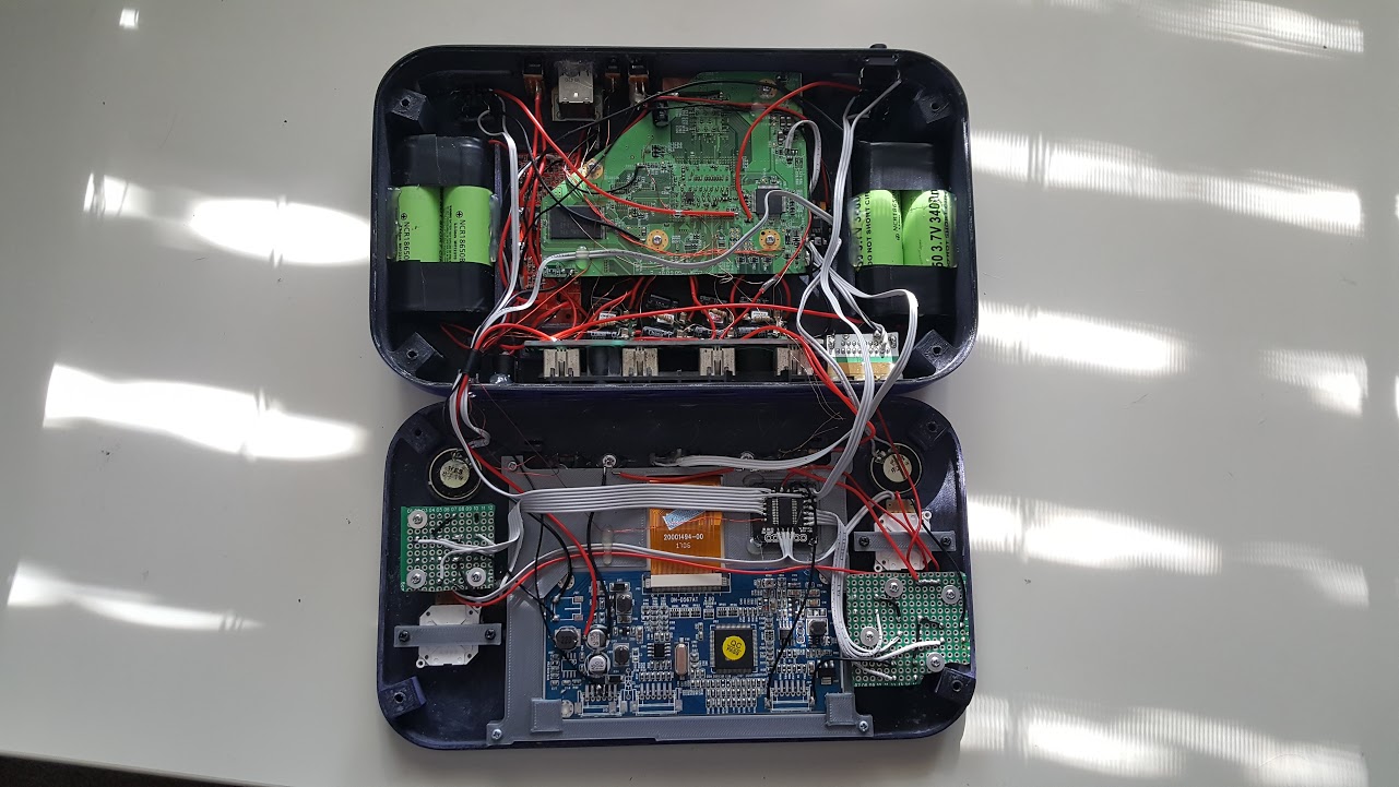 The finished internals
The display was modded to run from 5V by bypassing the 5V regulator on the driver board. For the controller, buttons and 3DS joysticks were connected to an open source microcontroller project called GC+ to emulate the controller. IR LEDs were placed in the front of the case to add Wiimote compatibility. Finally, the case was closed and the full system integration was complete.
Retrospective
This project took a year to complete after its initial inception. The internals are something I probably wouldn’t be proud of today, but for my first electronics project it was beautiful. The console still works 4 years after it was completed. I learned many new skills since beginning this project. I learned how to solder (even to tiny traces and vias!), how to use 3D CAD tools, and more about circuits than I had learned in school. It is truly valuable to work on a functional engineering project outside of academia. It becomes personal, and one’s passion can truly shine. Before I even finished this project, I had dozens of new and more ambitious projects I now wanted to complete.
See the full worklog here.